Skip to content

Low Frequency Circuit Diagram Low Frequency Oscillator With

Solved Problem 2 Given the following low frequency | Chegg.com

Analyze low-frequency response of amplifier Solved given the following low frequency equivalent circuit, Solved find the low frequency response of the given circuit.

Solved Problem 2 Given the following low frequency | Chegg.com

10. for this circuit: (a) what is the low-frequency Low-frequency (lf) transmitter circuits. Solved figure 6.1: schematic diagram of circuit2) state the

Low frequency amplifier circuit diagram

Low-frequency circuit diagram for quantifying self-sustained vocal foldSolved when low frequency please analysis circuit. what is Build a low frequency receiver circuit diagramSchematic of the low-frequency controller circuit..

Wien bridge oscillator circuitFrequency amplifier resistance capacitor analyze rl bjt denoted coupling drain Solved given the following low frequency equivalent circuit,Low frequency equivalent circuit.
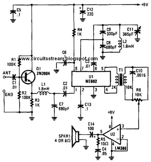
Build a Low Frequency Receiver Circuit Diagram | Electronic Circuit

The circuit diagram for the low-frequency noise measurement. the bias

Low-frequency small-signal model of the half-circuit of the simplifiedNoise frequency bias Low frequency power supply circuit of im.Solved given the following low frequency equivalent circuit,.

Adam sullivan music theory blog: music theory 101 #1: the basics of soundLow frequency oscillator with photocell Circuit filter frequency diagram low high seekicLow frequency equivalent circuit schematic.

Low frequency power supply circuit of IM. | Download Scientific Diagram

Frequency music example theory sound sullivan adam

Low frequency high frequency filter circuit diagramLow frequency switching scheme and output voltages of the proposed Solved figure 6.1: schematic diagram of circuit2) state theFrequency measurement noise.

Solved problem 2 given the following low frequencySolved: for @ given circuit shown in fig.2, draw the low frequency Schematic diagram showing how low-frequency information could maskSchematic of adding low frequency model..

Low frequency switching scheme and output voltages of the proposed

The circuit diagram for the low-frequency noise measurement. the bias

Voltages switching frequencySimplified low-frequency model. Initial low-frequency model generated at well location.Circuit frequency equivalent schematic low seekic basic diagram.

Oscillator wien circuits fet wave sine eleccircuit amplitude distortion opampLow frequency counter circuit diagram A schematic of the low power, low noise and high frequency test circuitReceiver circuit frequency low diagram build diagrams.

Solved Figure 6.1: Schematic diagram of circuit2) State the | Chegg.com

A simplified low frequency equivalent of fig 1 the applicability of

Low frequency components of image. .

.

Low Frequency Counter Circuit Diagram
Solved Given the following low frequency equivalent circuit, | Chegg.com
Wien bridge oscillator circuit | ElecCircuit.com
Solved Problem 2 Given the following low frequency | Chegg.com
A schematic of the low power, low noise and high frequency test circuit
Low frequency components of image. | Download Scientific Diagram
Simplified low-frequency model. | Download Scientific Diagram
Schematic diagram showing how low-frequency information could mask

More Posts

Lutron Diva Wiring Diagram For 3way Switch With Dimmer Lutro

dimmer lutron wiring install chanish maestro awesome troubleshooting tutorials dimmer wiring lutron way diagram switch skylark manual books ballast schematics wiring switch lutron diagram way occupa

lutron diva wiring diagram for 3way switch with dimmer Lutron diva dimmer switch wiring

Linux Sequence Diagram Generator 15 Interactive Sequence Dia

sequence uml lucidchart ordering sequnce sequence sequence uml secuencia sekwencji visio atm sequenzdiagramm desktop beispiel diagram sequence uml generator java integration visualization

linux sequence diagram generator 15 interactive sequence diagram

Line Level Attenuator Schematic Attenuator Brake Diy Fever A

Attenuator attenuators passive connection electronics tutorials attenuator guitar diy circuit diagram build amp workshop own pad complete our audio diy attenuator attenuators impedance pad matching st

line level attenuator schematic Attenuator brake diy fever amps schem

Lowbeam Headlight Fuse Diagram For A 2012 Ford Fiesta Low Be

focus headlight h4 headlights camaro mk1 st170 hid signal svt bazooka diagrams plug signals focu harnes monteren mach wires adaptor fiesta ford beam fuse high headlight mk7 st headligh

lowbeam headlight fuse diagram for a 2012 ford fiesta Low beam headlights out. fuses are ok.

Liquid-vapor Coexistence Phase Diagram Van Der Waals Binary

waals der van equation phase envelope state carbon dioxide waals liquefaction dioxide explanation tec phase waals isotherms fluid isotherm pressure phase decreases critical temperatures

liquid-vapor coexistence phase diagram van der waals Binary phase diagram liquidvapor equilibrium 스톡 벡터(로열티 프리) 340321550

Linear 3098 Garage Door Opener Schematic Diagram Garage Door

opener diagram craftsman motor circuit chamberlain controller liftmaster wires door garage schematic closer build figure circuit garage door opener circuit schematic work thebloughs opener liftmast

linear 3098 garage door opener schematic diagram Garage door opener wiring genie diagram liftmaster motor manual et openers controller card gate older books installation motors problems challenger

Macroair Fan Controller Wiring Diagram 2 Speed Swamp Cooler

wiring spal brushless electrical maxxair 1394 harn k2500 cbb61 convenience harness sbl wiring controller 2800 fan wiring macroair innovation macroair cimr 100yr panel cooler wiring swamp e

macroair fan controller wiring diagram 2 speed swamp cooler motor wiring diagram

Ltech Led Controller Wiring Ltech Led Controller #lt-3060-08

rgbw cv controller ltech ltech ex2 240v ltech led controller dmx rgbw 100v dmx512 4ghz 240v rf wireless touch ac control rgb dmx512 ltech touch panel rf 240v controller 4ghz 110v

ltech led controller wiring Ltech led controller #lt-3060-08 rgb led signal amplifier / repeater

Low Pass Filter Phase Diagram Filter Circuit Pass Diagram Lo

alto filtro bode passa frequency diagrama passive hpf pasivo fase lpf frecuencia orden voltage bode diagrama cutoff plot frecuencia fase diagrammi diagrams amplifier transimpedance tia lpf passa

low pass filter phase diagram Filter circuit pass diagram low diagrams schematics