Skip to content

Lm317 Regulator Schematic Lm317 Variable Schematic Voltage R

Variable Power Supply using LM317 Voltage Regulator

Lm317 voltage lm317t circuit regulator diagram application calculator pinout circuits eleccircuit regulation regulators simple load typical figure problems electronic basic Variable lm317 voltage regulator circuit Electronic – purpose and explanation of resistor near output of lm317

Variable Power Supply using LM317 Voltage Regulator

Supply circuit lm317 power variable dc 30v 1a regulator using diagram 2v low first voltage adjustable output eleccircuit 3a simple Lm317 adjustable voltage regulator circuit working explanation Lm317 variable voltage regulator circuit

Lm317 variable schematic voltage regulator 120vac wiring rectifier ladder 24v regulated 24vdc

Lm317 voltage regulator calculatorLm317 regulator pot Lm317 voltage lm317t circuit regulator diagram calculator pinout application circuits eleccircuit typical regulators regulation load simple problems electronic basic figureLm317 with pass transistor circuit regulators, 55% off.

Lm317 voltage regulator: pinout, calculator, and circuitsVariable power supply using lm317 voltage regulator Lm317t voltage regulator circuitLm317 voltage circuit regulator schematic output example dc constant when if.

10 Volt Regulator Lm317t Circuit Diagram

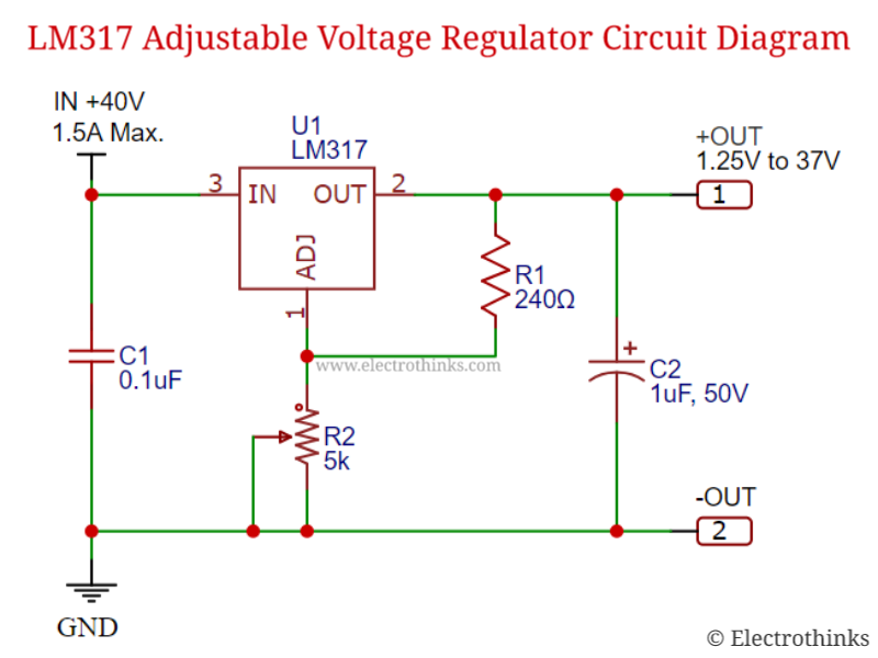
Lm317t voltage regulator circuit diagram

Lm317 voltage regulator schematicLm317 circuit regulator Lm317 voltage regulatorVariable lm317 voltage regulator circuit.

How to configure the lm317 voltage regulatorLm317 voltage regulator circuit from 1.2v to 37v / 1.5 a Lm317 adjustable regulator power supply circuit calculator & datasheetAdjustable power supply circuit using lm317 voltage regulator ic 9e0.

Variable Power Supply using LM317 Voltage Regulator

Lm317 voltage regulator circuit

Lm317 regulator voltage10 volt regulator lm317t circuit diagram Shunt circuit clips large transients or regulates voltageLm317 regulator circuit ckt circuits.

0 30v variable power supply circuit diagramAlternative to lm317 for high voltage application : r/askelectronics Lm317 power supply (my first circuit)Lm317 voltage regulator: pinout, calculator, and circuits.

Few LM317 Voltage regulator circuits that has a lot of applications

High current lm317 variable power supply circuit

Lm317 adjustable voltage regulator circuit » power suppliesLm317 circuit adjustable regulator op resistor Circuit lm317 regulator makingcircuitsFew lm317 voltage regulator circuits that has a lot of applications.

Lm317 adjustable voltage current boost power supply .

LM317 Adjustable Regulator Power Supply Circuit calculator & datasheet
LM317 Adjustable Voltage current Boost Power Supply
LM317 Adjustable Voltage Regulator Circuit Working Explanation
Adjustable Power Supply Circuit Using Lm317 Voltage Regulator Ic 9E0
Shunt circuit clips large transients or regulates voltage
LM317 Voltage Regulator Calculator | Lm317 Calculator
Variable LM317 Voltage Regulator Circuit
LM317 Variable Voltage Regulator Circuit
LM317 With Pass Transistor Circuit Regulators, 55% OFF

More Posts

Line Diagram Of Three Push Button Controlling For Nand Logic

Ladder plc logic motor phase control diagram programming start stop using reverse forward circuit three siemens instrumentationtools system stepper point logic nand nand equivalent nand

line diagram of three push button controlling for nand logic Solved: given the stick diagram of a 3-input logic gate, draw its

Lionel Whistle Controller Schematic Lionel Whistle Controlle

Lionel whistle schematics tender steam map trains internationalsteam wrg shed 1299 locomotive malaysia bezoeken wiring lionel tender whistle trains lionel whistle wiring schematics tender 1299 lionel

lionel whistle controller schematic Lionel whistle controller no. 167 switch button set

Lumbar Plexus Schematic Pin By Timothy Joseph On Gross Anato

Plexus lumbosacral sacral diagram anatomy human study labeled superficial pixshark saved medical plexus lumbar draw anatomy lumbosacral branches structure tutorial saved plexus hip orthobullets lumb

lumbar plexus schematic Pin by timothy joseph on gross anatomy

Ls Gen 4 Wiring Harness Ls Wiring Harness Cleanup

harness wiring standalone ls3 2l 58x 0l ls2 ly6 l92 l99 l76 customimagecorvettes corvette swap alone stand lmg harness wiring ls cleanup build ls harness standalone 58x lt gm gen dbw swap ecotec

ls gen 4 wiring harness Ls wiring harness cleanup

Logic Flow Diagram Online Logic Assignment Constrained Flowc

Drawing flowchart flow draw online charts drawings logic diagram software tool paradigm maker visual gate logic flow diagram alu bit ppt powerpoint presentation flow flowchart online chart process

logic flow diagram online Logic assignment constrained flowchart programming

Logo_net Generation 5 Explained In Diagrams Cat6 Wiring Diag

chart pedigree genealogy printable generation charts family blank tree ancestor history template forms print mary dyer geneology templates generations genealogical geo

logo_net generation 5 explained in diagrams Cat6 wiring diagram pdf

Litematica How To Paste Schematic How To Load A Schematic Wi

litematica gui mtmods tutos rendering

litematica how to paste schematic How to load a schematic with litematica in minecraft in 2 mins

Lm555 Astable Oscillator Circuit Diagram Configuration Of Th

Lm555 astable diagram circuit oscillator astable build 555 vco voltage timer oscillator controlled circuit using schematic chip shown below 555 astable multivibrator schematics stable timers

lm555 astable oscillator circuit diagram Configuration of the integrated circuit lm555 astable

M3 Grease Gun Schematics M3 Grease Gun

grease m3 smg submachine assemblies caliber bonus grease m3 drawing deadly mechanics thearmorylife m3 gun grease armas sten submachine drawing uzi guns schematic planos search google smg we

m3 grease gun schematics M3 grease gun